|
PD Center Home > About Japanese PD system

In 2002, stress corrosion cracks(SCC)were found in BWR Primary Loop Recirculation(PLR)piping that are made of type 316L low carbon stainless steel. Through wall depths of these SCCs were measured only by shear wave tip diffraction technique, and following destructive examination revealed that some SCCs tips were penetrating into weld metal and UT sizing only by shear wave tip diffraction technique have a possibility to underestimate. Most probable reason of this undersize was estimated that shear wave was attenuated in the dendritic structure of the austenitic weld metal. Therefore, reliable SCC depth sizing technique and UT certification system (PD) was required!
“UTS” and “RRT “ and In-Plant Test
UT method of SCC depth sizing was improved based on the national project, “UTS”.
On UTS, a round robin test and in-plant tests were carried out as a blind test to verify the performance of UT method by using longitudinal wave.
As a result, UT measurement by using refracted longitudinal wave was verified to be effective in depth sizing of SCC.
On, Sep., 2004, Nuclear and Industrial Safety Authority (NISA) agreed that the modified depth sizing UT method by using longitudinal wave is effective. + 4.4mm (safety redundancy) to depth measured is required for FFS SCC growth evaluation.This safety redundancy would be withdrawn when the depth was sized by PD qualified personnel.
Dec., 2004, PD System Preparatory Committee was organized in JSNDI to build up the JPD qualification examination system (members: regulator/ academics/ utilities/ inspection societies/ vendors). The PD system preparatory committee members reviewed ASME Code Section XI Appendix VIII and ENIQ. Because of explicit description of testing methodology and acceptance criteria, it was decided Appendix VIII would be suitable for the Japanese qualification examination.
On June, 2005, “NDIS 0603: Qualification and Certification of personnel for performance demonstration of ultrasonic testing systems” was issued. On Dec., 2005, NDIS 0603 was reviewed and accepted to be adequate by the nuclear safety committee of NISA.
Page Top
Japanese PD organization
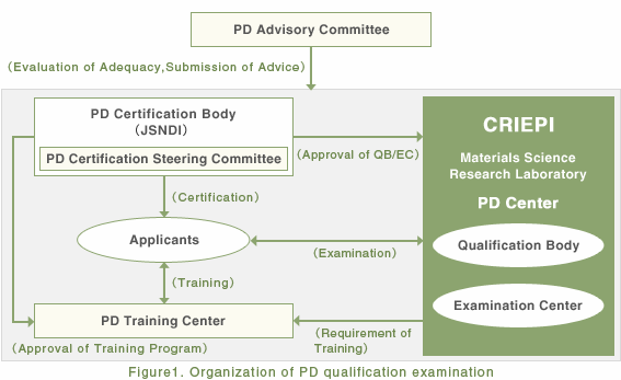
Figure 1 show the organizations that participated in the PD qualification examination of crack depth sizing of austenitic stainless steel pipe welds in the nuclear power plant.
The PD advisory committee is posted to the top of PD qualification system.
PD advisory committee
- is posted to the top of PD qualification system.
- reviews activities of PD related organizations and make recommendation to them.
PD certification body (JSNDI)
- certifies PD related organizations.
(JSNDI took this role because they have a long term experience of NDE personnel qualification. )
PD qualification body (CRIEPI)
- organizes qualification examination
(i.e. prepares test specimens, test facility and quality control document. )
- manages PD qualification examination and maintains test results and control document.
PD examination center (CRIEPI)
- operates PD qualification examination under the direction of the PD authorized qualifying body.
PD training center
- training for re-test within 30 days.
- annual training for license renewal

Page Top
Overview of Japanese PD
- ・Scope:
- Crack depth Sizing for Austenitic Stainless Steel Piping of Light Water Nuclear Power Plant
- ・Test specimen:
- Butt welded austenitic pipe with SCC
- 1) At least 10 IGSCC
Cracks in the depth sizing sample set are to distributed according to the specifications in Table 1.
The remaining IGSCC shall be in any of categories.
- 2) At least one IGSCC should be deeper than 15mm
- 3) At least the tip of IGSCC should penetrates into the weld metal.
- 4) Three types of pipe size (Table 2)
■Table 1 Specification for distribution of flaw depth.
Flaw depth h
(% wall thickness) |
Minimum number of flaws |
| 0< h ≦30% |
2 |
| 30< h ≦60% |
2 |
| 60< h ≦100% |
2 |
■Table 2 Nominal diameter and wall thickness of test specimens.
| Nominal Diameter (mm) |
Wall thickness (mm) |
| 600 |
35 |
| 350 |
25 |
| 150 |
10 |
- ・Acceptance criterion of the examination is as follows:
-
- 1) The RMS (Root Mean Square) error of the flaw depths estimated by UT does not exceed 3.2mm as compared with the true depth.
The remaining IGSCC shall be in any of categories.
- 2) No flaw depth estimated by UT is underestimated by more than 4.4mm, compared with the true depth. (This we have dubbed a “critical miss call“)
Page Top
|
|


